With the deeper understanding of the pressure drops and flow channels the cooling systems can be optimized and unnecessary costs and oversizing or undersizing can be avoided. Cooling station oversizing may cause:
- Extra purchasing costs
- Higher energy consumption creating continuous extra costs
- Pump cavitation that might lead to pump failure
- Too high flow rate in the process components that might cause cavitation or increased pressure in cooling system
- Larger footprint and more weight
- Extra designing and installation work that increases the project costs and prolongs the duration of the project
Cooling station undersizing may cause:
- Reduced flow rate which leads to reduced cooling power
- Extra designing- and installation work that increases the project costs and prolongs the duration of the project
Understanding the basics of the pressure losses is not complicated and it may save a lot of money and time.
Cooling station optimization
The pressure losses are strictly connected to the flow rate, and it is very important to understand the relation between the pressure and the flow rate. It is also very important to understand how the desired flow rate is achieved. A Cooling system pressure head is defined with the capacity of the pump and the resistance of the system to the flow. The capacity of the pump can be viewed from a pump specific H/Q diagram and the resistance of the system to the flow can be viewed from a system diagram. The operating point of the cooling system is at an intersection of the H/Q diagram and the system diagram as shown in Figure 1.
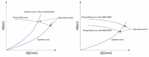
The desired coolant flow can be obtained by selecting a correct sized pump for the cooling system. Increasing the size of the pump impellers increases the flow rate of the pump. Increasing the number of pump impellers increases the pressure head of the pump. To acquire a more specific operating point the H/Q diagram of the pump can be moved upwards and downwards by changing the pump rotation speed (Figure 1). This moves the intersection of the pump H/Q diagrams and the system diagrams. The rotation speed of the pump is changed by using a frequency converter. The system diagram can also be moved by using flow control valves or bypass channels (Figure 1), but this leads to higher energy consumption and oversizing which should be avoided.
Defining the correct operation point accurately is often difficult, because all pressure losses in the cooling system are not known. This may lead to oversizing or undersizing. To correctly size the cooling station, it is very important to know all pressure losses in the cooling system as accurately as possible in order to determine the system diagram. The H/Q diagram of the pump is always known very accurately, and it can be manipulated if needed. The internal pressure losses of Adwatec’s cooling system are defined so the pressure head available for customer’s use is known.
Flow distribution
The flow distribution in the coolant lines and the pressure losses are often misunderstood leading to incorrect sizing. There is a big difference in the pressure losses depending on whether the components are installed in parallel channels or in line.
The pressure losses are also dependent of the flow rate. As the system diagram shows the pressure losses increase exponentially when the flow rises. If the flow rate doubles, the pressure losses quadruple.
In parallel lines the pressure drop is always the same in all branches, if the pressure is measured from points A and B as shown in Figure 2.
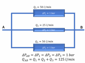
If one of the channels has a bigger resistance to the flow, it’s flow decreases equalizing the pressure drop between all channels. The pressure drop is the same in all branches. In this case there are ways to determine the pressure drop factor to calculate the pressure drop and the flow rate between points A and B.
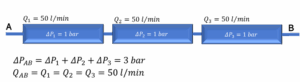
If the components are in line the pressure drop calculation is much more straight forward and pressure drops are just added together as shown in Figure 3.
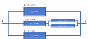
The coolant line might be a complex system as shown in Figure 4 and there might be only indicative values of how much pressure losses there are in the channels. The required flow and the total flow through the channels are always known, but if the flow resistance in the channels is not controlled the flow rates in each channel cannot be controlled either.
In this case the flow control valves must be added to equalize the flow resistance in the parallel channels as shown in Figure 5.
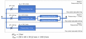
The flow control valves have their own system diagrams that can be used to determine the flow rate that goes through the valve by measuring the pressure drop in the flow control valve. In Figure 5 the pressure drop would be equal in all channels without the flow control valves, but the flow rates would not be at the desired level. The pressure drop between points A and B would be somewhere between 1,5 bar and 2 bar and the flow rate would be lower in branch a, and higher in branches b and c. When the flow is restricted in branch b until the flow rate is 60 l/min and at branch c until the flow rate is 30 l/min all channels have the same 2 bar pressure drop and the desired flow rate.
If the pressure losses are known in the power electronics or in the battery modules the whole coolant line pressure losses can be estimated by using a configurator at Adwatec’s website. Adwatec’s configurator has a simple pressure loss calculator that can be used to calculate the pressure losses in the pipelines. In case of any questions Adwatec’s technical team is always eager to help and inform.
WORDS:
Veikko Verronen
R&D Engineer
+358 40 771 9460
veikko.verronen@adwatec.com